 Logic
Logic
INTRODUCTION
This component allows you to perform Boolean operations (AND / OR / XOR / NOT). This is done when the status of one of the inputs change. There is the possibility to define, for each input, whether to consider changing the ON / OFF or OFF / ON. You can define up to 4 outputs, each of which will acquire the value resulting from the operation.
USE CASES
- The user can use this component to calculate parameters coming from the load control and perform a result out of it.
COMPONENT’S PROPERTIES
GUI
This component’s sample is made by using Graphic UI gateway.
Please refer to “Gateways / Protocols” guide in order to get further info.
INPUTS:
Input: Drop Down, Color Info, Text info, Switch, Lock, Pulse component;
Evaluate when:
– Input “n” changes from Off to On: operation is carried out only when the input goes to On;
– Input “n” changes from On to Off: operation is carried out only when the input goes to Off;
– At any change of the Input “n”: operation is carried out anytime input goes to On and Off;
Invert value: a checkbox that allows inverting the input values into 0=On, 1=Off;
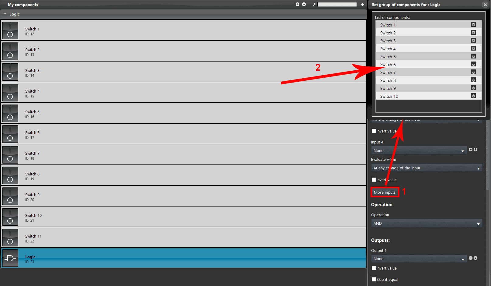
More inputs:The component’s parameters area allows you to take into account up to 4 different inputs. However, you can add countless inputs to the operation. To do this just drag & drop the required inputs into the dialogue box which appears after clicking “More inputs” button.
OPERATIONS:
They define the circumstance under which the logic is executed.
– AND: Only when all the inputs behave as defined, the operation is carried out;
– OR: Only when one or another input behaves as defined the operation is carried out.
– XOR: The output is “true” if either, but not both, of the inputs are “true”;
– SUM: This does the sum of all the inputs that need to be Info components. This logic allows to sum 2 values coming from two energy meters;
– AVERAGE: This operation does the average of the all the inputs. This logic can be applied to get the average of multiple values coming from three separeted Termostats that have been installed within a single enviroment to get the average temperature;
– MAX: This operation does the max of all the inputs as Info components;
– MIN: This operation does the min of all the inputs as Info components.
OUTPUTS:
Output: Drop Down, Color Info, Text info, Switch, Lock, Pulse component;
Invert values: Checkbox that allows inverting the output values into 0=On, 1=Off.
Active inputs counter: Info component that shows the number of inputs that are currently On;
HELP
Logic configuration can be easily carried out by using component’s drag&drop function. When setting components on Component’s parameters, you can use the drop-down menu, or you can drag and drop them from “My components” area to the component selection field.
Reminder before continuing:
- Download and Install EVE Logic plugin to enable plugins (link);
- After loading .eve project to the server, run EVE Remote app, log in and then wait a couple of minutes for logics activation.
LOGIC COMPONENT PROJECT EXAMPLE WITH MORE THAN 4 INPUTS
Step 1:
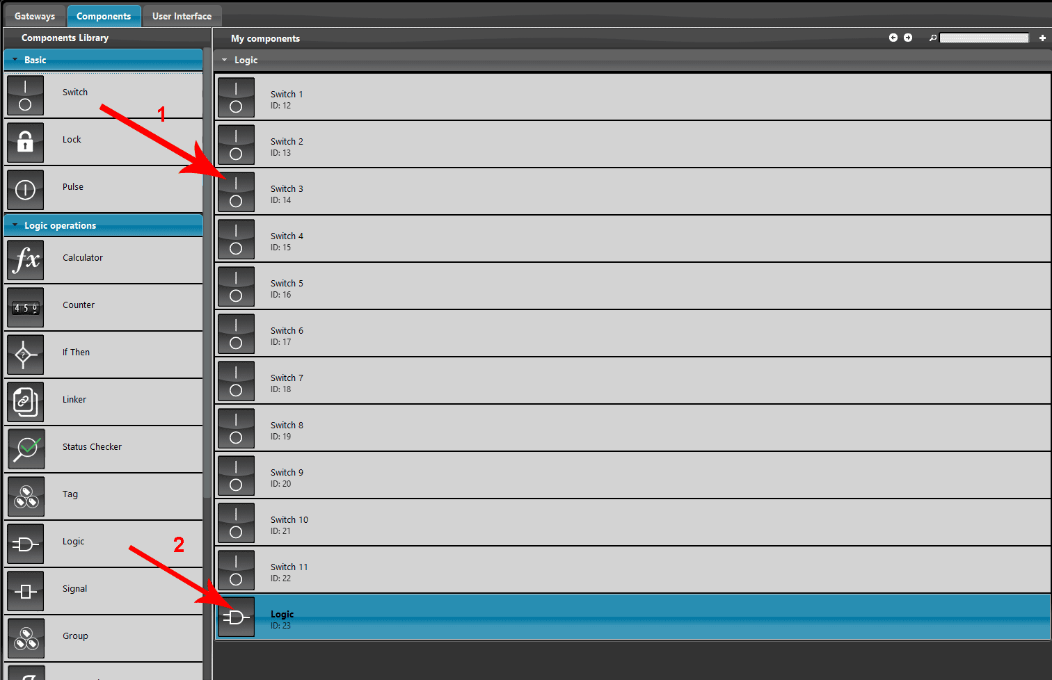
Add a new Logic component and 11 switch components into the project.
Now click on the button More inputs, a new window will appear on the EVE Manager screen. Add all the components switch inside the list by drag and drop function or double click on them.
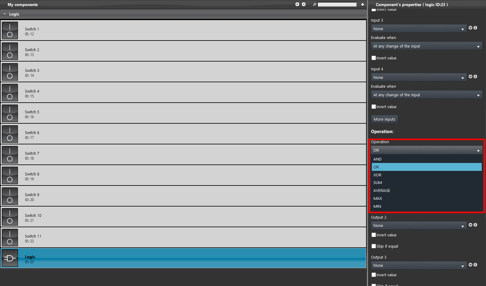
Select the type of operation. In this example we will use the “OR” operation.
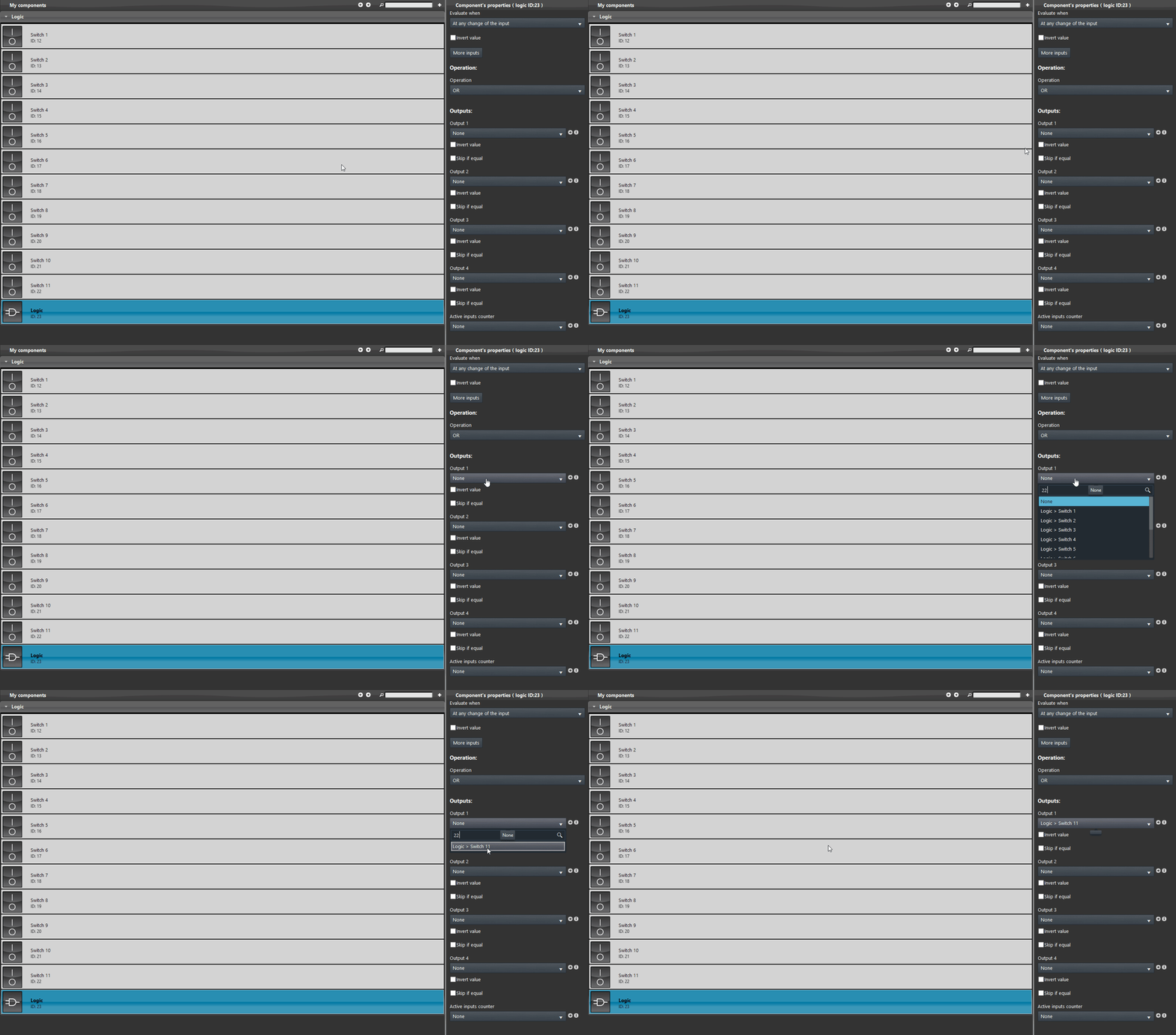
Now add the output component. In the first Output dropdown select the last switch component available.
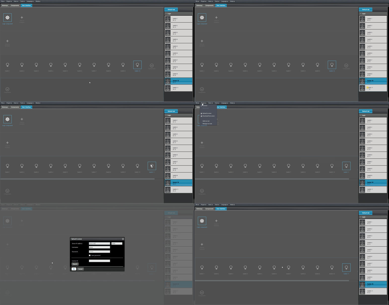
Finally add all the component apart from the logic component into the User interface and upload the project into the server.
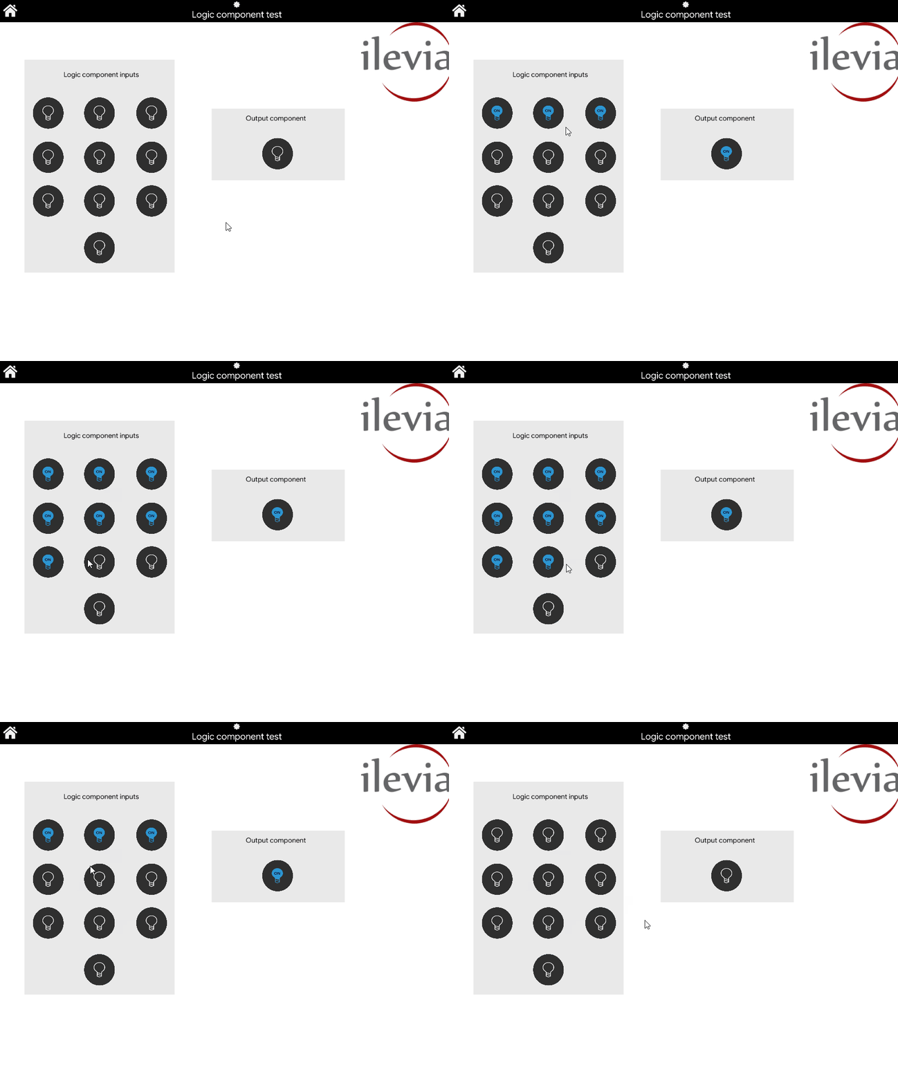
LOGIC OPERATION VISUAL RESULT
This below is a reppresentation of the Logic configured in the previous steps. As you can see, once one of the input component is pressed the output will change its state accordingly.
Clicca il link per poter scaricare il progetto dell’esempio per provarlo.


