 VIRTUAL THERMOSTAT
INTRODUCTION
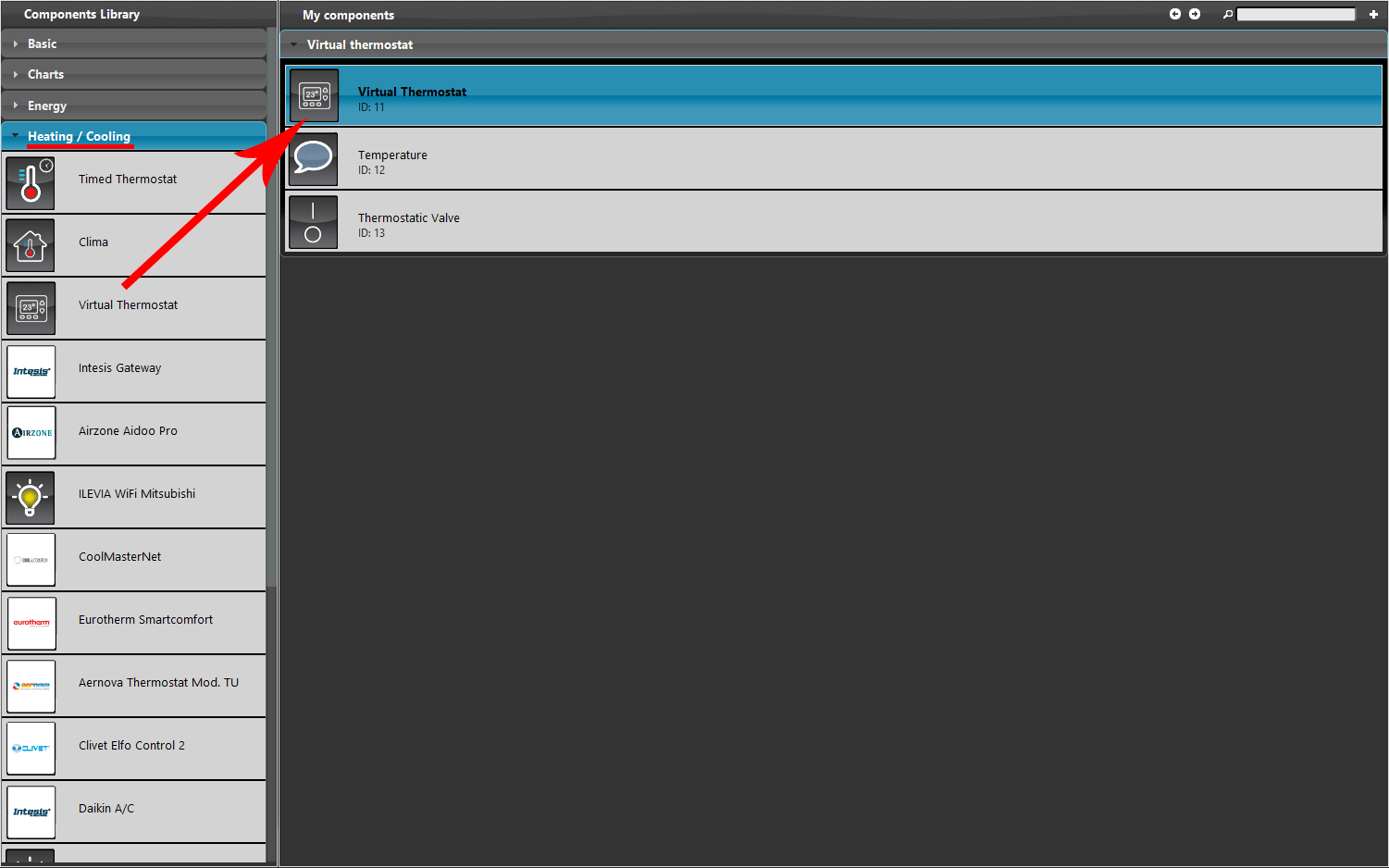
This component make possible to configure a virtual thermostat logic within the Ilevia server. This component comes handy when the thermostat components are separate and no controlled by one device.
USE CASES
- In the plant where the Ilevia server is installed doesn’t have any wall mounted thermostats.
COMPONENT’S PROPERTIES
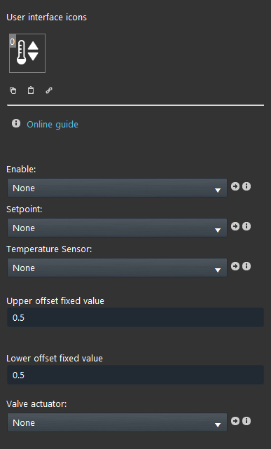
Enable (optional): By linking a Switch component, to enable or disable the entire virtual thermostat function;
Setpoint Link a Setpoint component, this component will set the temperature through a logic;
Temperature sensor: Link the Info component that display the current temperature;
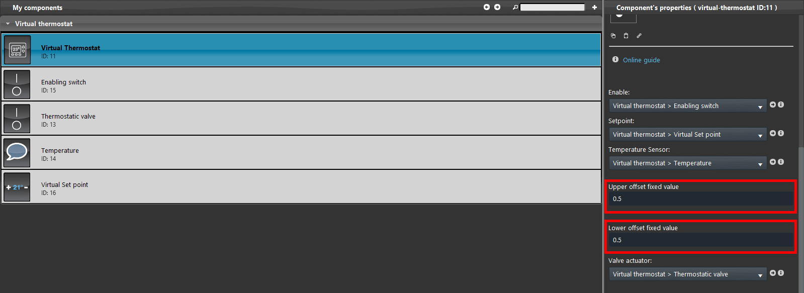
Upper / Lower offset value: These two values will set the hysteresis that will be taken by the Ilevia server to know which is value range in which the actuation will be applied;
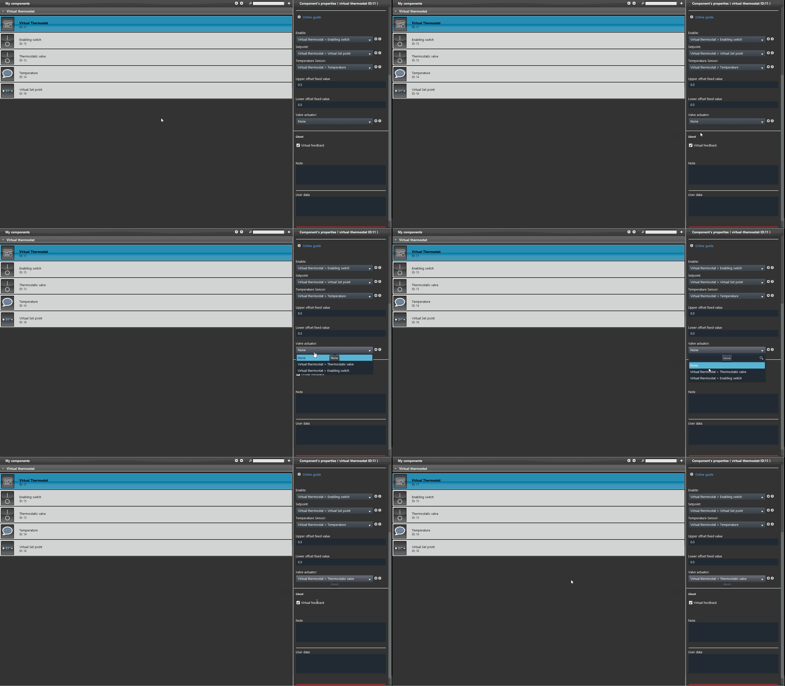
Valve actuator: Link a Switch component that will be set in order to actuate the thermostatic valve.
STEP BY STEP COMPONENT CONFIGURATION
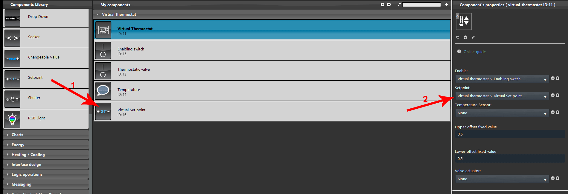
1. Add the switch component. 2. Then set it as the enabling component for the entire Virtual thermostat.
1. Add a new Setpoint component, make sure it has EVE-GHOST as its gateway, 2. then link it with the drop down menu called Setpoint.
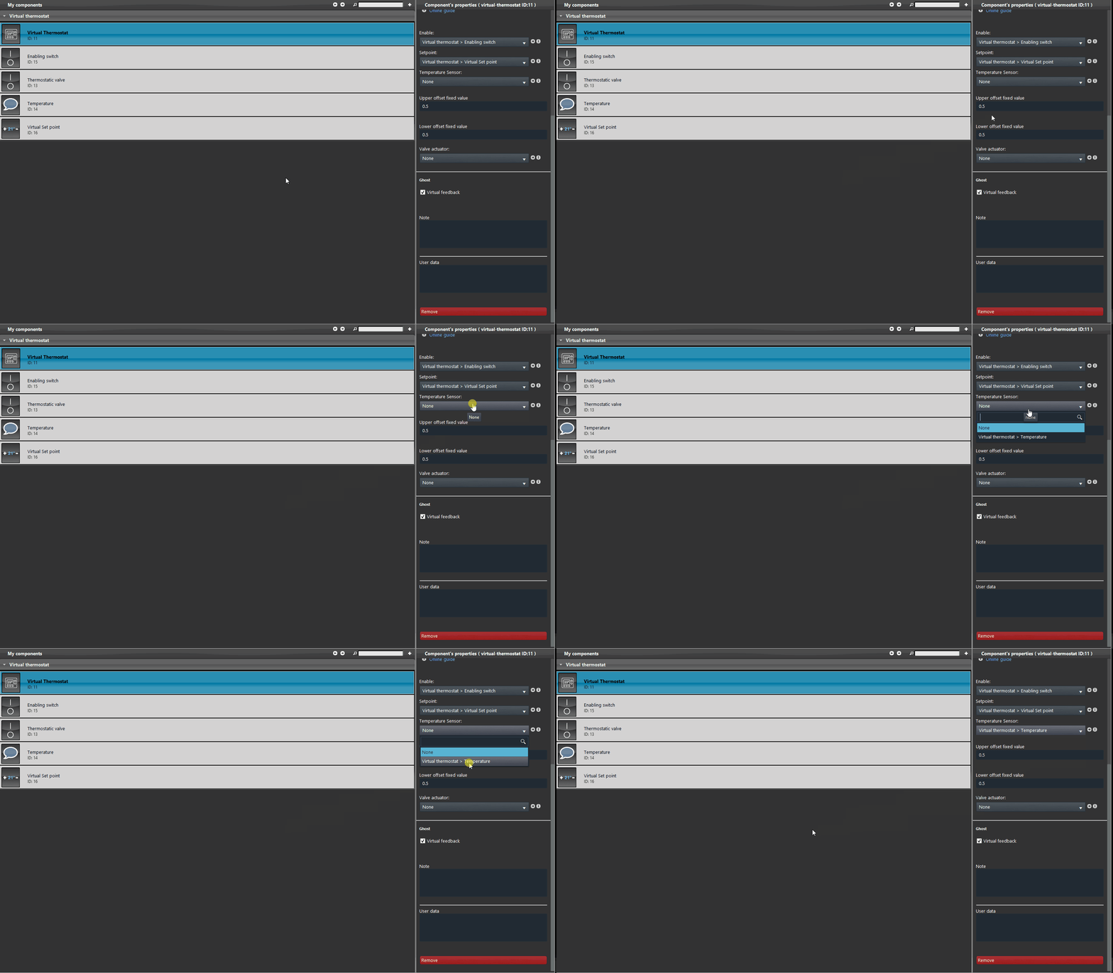
Add the info component that is configured to display the temperature value and link it to the drop down menu called Temperature sensor.
Finally add the Switch component that is configured to actuate the valve and link to the drop down menu called Valve actuator.
Then adjust the Upper and Lower offsets according to your necessities. This will set the hysteresis values which will trigger the Valve.
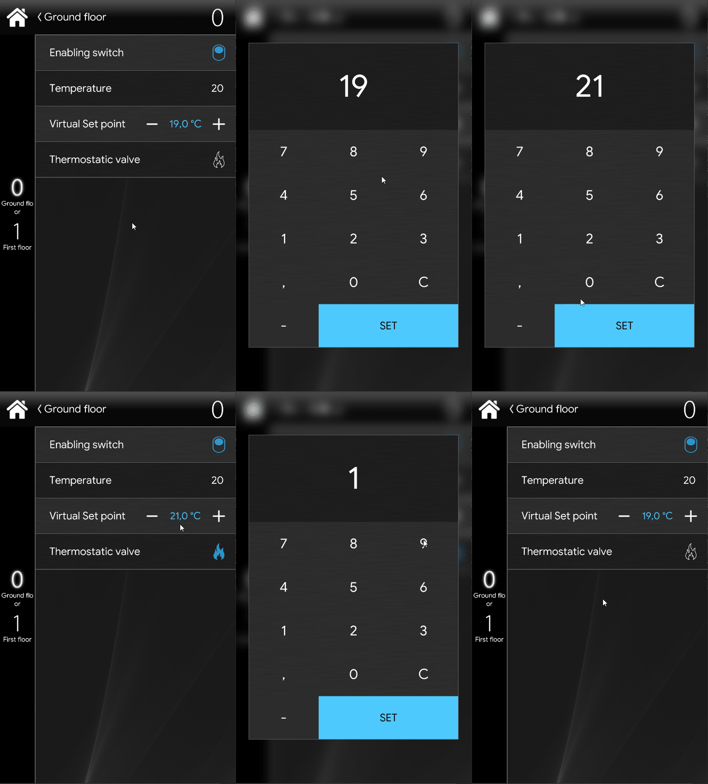
CLASSIC INTERFACE
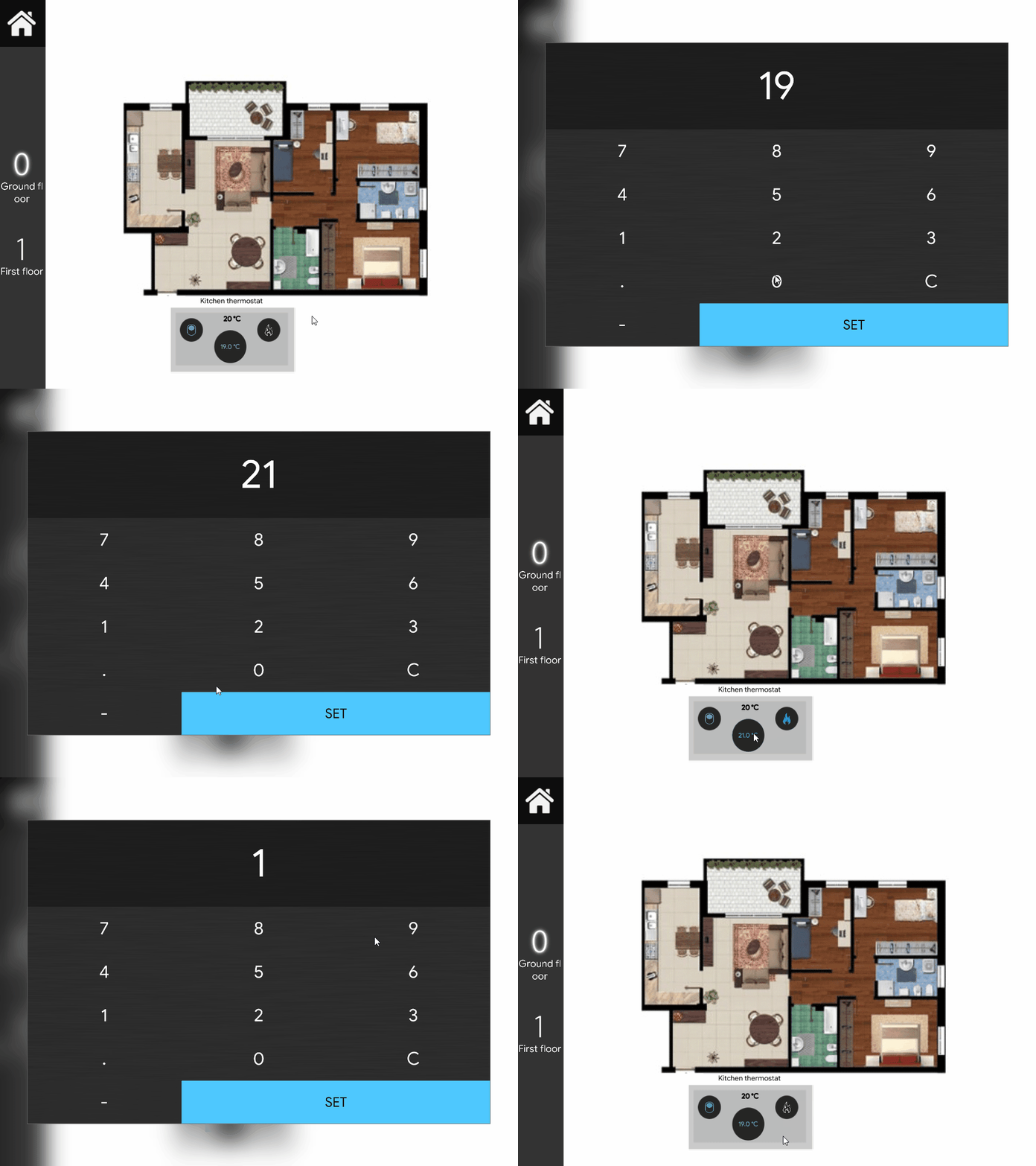
MAP INTERFACE
This is the final result of how a virtual thermostat could look like within the Map user interface.

